|
|
|
|
|
This week's topic:
Canada Air Pilot, Part 2: Approach Plates
Moving along just a little further, we'll take a look at the Approach Plates found in the Canada Air Pilot, our reference for IFR information for approach and departure at the various airports in Canada with published instrument procedures. There is a lot of reading here this week.
Approach Plate Example
Outside the Box Information
Multiple
Approaches on One Plate
Different Panels
Header Bar
Approach Diagram
Symbols
Safe Altitudes
Bearing, Track, Transition Altitude Information
Transitions
Highest
Terrain/Obstruction
Cautionary
Information
Other
Details
Profile Details
Missed Approach Instructions
Primary and Secondary Instructions
Minima Box
Straight-In Landing Minima
Circling Minima
Missed Approach Point
Airport Diagram Details
Flight
Times
More Details
DME Arc Transitions
Intermediate Fixes
RNAV Initials
Clearances Required for These!
Cautionary Note for Back Course
"A" Example
Off-Angle Approach
Notes
Aircraft Categories
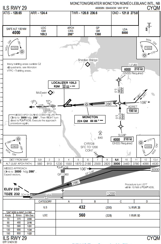
Like the airport diagrams discussed a couple of weeks ago, there are several "panels" of information on each one. I'll show you an example, in this case a drastically outdated plate for the ILS RWY 29 at Moncton/Greater Moncton Romeo LeBlanc International Airport, CYQM:
The information "outside the box" above and below the main portions of the chart is the same as the Airport Diagram plate, with the addition of the Aerodrome Reference Point (geographical coordinates) discussed in that topic. This information now resides near the top of the page, underneath the name of the airport. The name of the approach shown should appear above and below the main box on the left hand side printed in ALL CAPITALS. ATC should be referring to this procedure by this name on the radio when clearing an aircraft to fly this approach procedure. Some examples:
Some approach plates offer information on more than one approach. This was more common in the past when ILS approaches that used NDBs as the Final Approach Fix (FAF) also had an NDB approach procedure based on that NAVAID, but is becoming increasingly rare as NDBs are being decommissioned across the country. Additionally, when this article was originally written almost 20 years ago, GPS Overlays were published in many places such that an aircraft could use the approach plate for the procedure, but navigation was actually done by GPS instead. Of course, this has all changed in that RNAV has become much more widely accepted in the intervening years and most RNAV approaches are published separately..
We'll look individually at the panels on the plate now to attempt to clarify the purposes of each, and the symbology and terminology found on each.
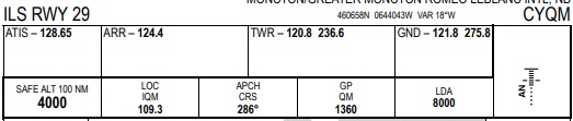
The top panel, just as with the Airport Diagram and the SID plate, contains the list of frequencies for use by IFR flights and the unit names (where other than the name of the airport). This was covered in previous topics (IFR Flight Part 2: Departures for the SID plates, and Charts Part 1 CAP: Subpart A: Airport Diagrams). Below this top line are some boxes containing the important numbers associated with this procedure, such as the 100 NM Safe Altitude, final approach course, Localizer frequency (if applicable), the Final Approach Fix (FAF) Crossing Altitude and the runway length. At right is a diagram with a code to show what kind of lighting a pilot can expect at the runway this approach procedure serves.
Notes for the 100 NM Safe Altitude: If a pilot becomes disoriented or in other trouble, as long as the aircraft is within 100 NM of the aerodrome, this altitude is safe in terms of obstructions and terrain. This altitude includes 1,000 feet above known obstacles and terrain within 100 NM of the airport (or 1,500 or 2,000 feet in the Designated Mountainous Areas on each coast as appropriate, and 2,000 feet is provided if this 100 NM radius reaches into US airspace, as well). They tend to be high due to the broad range of area they encompass.
The Approach Diagram contains a ton of information, even for a simple approach. In this case, the ILS RWY 29 plate above shows many, but not all of the items commonly found on the average approach plate. I've cut the image down a bit and labeled some items right on the image included below. Have a look.
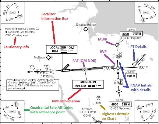
First the symbols. They meet the same standard of symbols as found on the legends of many IFR charts. Detailed here in RED are NAVAIDs associated with the approach procedure, in this case the Localizer with a data block containing the frequency and Morse Code identifier and the QM NDB (which serves as te FAF on this procedure). VORs, VORTACs, NDBs, Localizers and Fixes/waypoints not associated with the procedure or the missed approach are not drawn. The Morse Code combination for the IDENT is provided so a pilot can tune in the NAVAID and listen to the transmitted code and confirm the correct NAVAID is selected. This is important if there is more than one Localizer or NDB near the airport as misidentification of tuned NAVAID can lead to horrible consquences in IFR conditions. More information on each type of NAVAID can be found in last week's topic on NAVAIDs and Instrument Approaches.
Noted in GREEN, the "quadrantal altitudes" are the 25 NM Safe Altitudes. They are located in the four corners of the diagram, and represent their appropriate quadrants (NW, NE, SW, and SE) out to 25 NM radius (with a 4 NM buffer) from the fix noted, typically the FAF or the Aerodrome Reference Point (ARP). These altitudes represent at least 1,000 feet above the highest terrain or obstacle (whichever is higher) within the quadrant drawn and, while being certain to meet any published restrictions, may be used by a pilot as guidance as to what minimum altitude can be flown in the given area. Note that the aircraft may be outside controlled airspace if you're at one of these altitudes, but you'll be above known obstacles and terrain. The circle described is often broken up into "quadrants" allowing for lower altitudes in certain ones and higher in others based on the existence of terrain or obstructions. You have to know where you are in relation to the fix to figure out if you're safe with these areas. In some areas, circling procedures are banned in certain directions. Notes regarding this will be published in the Approach Diagram, and the prohibited portions will be marked within a similar circle, located elsewhere within the Approach Diagram.
Waypoints are labeled in PURPLE. These include the Initial Approach Wapoints (IAWP, both left and right are drawn on this approach), the Intermediate Waypoint/Intermediate Fix (IWP and IF, respecitvely) and the Final Approach Fix (FAF). It's important to note any altitude and speed restrictions that may apply to these fixes. In this example, both IAWPs are marked as "at or above 4,000, maximum 210 KIAS" and ADRET is marked as "Maximum 190 KIAS". ATC assign lower altitudes to a pilot, but unless these restrictions are explicitly cancelled by the controller, the pilot is expected to fly them while descending to the assigned altitude. For example, a pilot clear to fly the the SUVIP transition and assigned 3,000 must still cross SUVIP at 4,000 or above. Controllers should keep this in mind, as well, since it's sort of like setting a pilot up for failure to clear an aircraft to an altitude below that of a published restriction.
Printed in BLUE text on the diagram clip above you'll find Bearing, Track, and Transition Altitude information, as appropriate, for each course specified on the diagram. This includes the Final Approach Course (FAC) for the localizer, the tracks and minimum altitudes for the initial approach segments (these segments run from SUVIP and LEVIB to ADRET, and GNSS (RNAV system based on Global Navigation Satellite System like GPS) is required for an aircraft to fly these transitions, as noted on the approach plate itself).
We'll start with the Localizer. This is normally a two-toned arrow with pink on one side if done in color (or grey if in black and white) and white on the other. The course for the localizer centerline is printed within the arrow next to another smaller arrow pointing in the direction indicated for the inbound track. Where Procedure Turns (PT) are provided for, the outbound course will also be printed next to an arrow pointing away from the airport, as are the headings for the procedure turn (45° off the final approach course and its inverse) and an arrow in the picture demonstrating which side of the final approach course where the procedure turn should be accomplished. Not all approach procedures allow for PTs, and those without such procedures will not have these details. Notes will be published indicating "straight-in approaches" only in such cases. Straight-in approaches will be discussed a little further below. RNAV approaches will not have Procedure Turns, as their purpose is to allow an aircraft to navigate waypoint to waypoint to avoid such a requirement.
There may be published transitions for an approach from neighbouring fixes and NAVAIDs that make up airway segments. Years ago, the ILS RWY 29 at Moncton had transitions published including tracks and altitudes from the YQM VOR and the ZQM NDB. These were removed when the redesigned approaches were published, but other procedures contain examples of these. They will be listed in fine print with tracks drawn between the fixes to which they apply.
In the GOLD text, I have pointed out one more little detail. In the diagram, which is typically centered on the FAF, the highest obstruction or terrain is indicated. In the case of an obstruction like a tower, it is drawn as an inverted 'V' with a dot in it. The height is given in feet ASL. Note there may be many other obstacles and terrain points present, but only the highest known of both is shown. If the highest point is terrain, it will be marked solely as a dot with the elevation next to it.
Another important spot to look when reviewing an approach plate is the upper left hand corner. Any notes regarding the use of the approach, be they restrictions or just information, will reside there. For older Localizer Back Course approaches and current Localizer approaches (those without glidepath antennas), there is a cautionary regarding glideslope indications. If use of a remote altimeter setting (from another nearby station) is authorized, the altitude to add to each altitude published in the approach procedure is provided. If restricted airspace is nearby, a cautionary note about that is printed, here, too. The list goes on and on. If ever in doubt about the meaning of a note, by all means, ask your friendly neighbourhood ATC for clarification.
There may be other things shown on the approach diagram as well. Restricted airspace is plotted out, often with additional descriptive text. Rivers, lakes, and even rough outlines of cities (visible at the left edge of the 10 NM circle in the above example) are drawn for pilot reference. Nearby aerodromes and helipads are plotted, as well. For published Visual Approaches, which I haven't detailed, prominent visual landmarks will be drawn in rough form to help guide pilots, as well things like railway humpyards, major highways, etc.
The first box under the approach diagram is the home of the Approach Profile Detail. Here is an example, taken from the same ILS RWY 29 for CYQM.
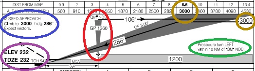
Here you can see the approach in a not-to-scale side view. Near the center of the diagram you can see a grey, inverted cone which represents the position of the Moncton NDB (QM) in this example, which is the FAF. Assuming a pilot was to go overhead the QM outbound for a procedure turn (pointing to the right, in this example), the track of 106° is marked on the "localizer fan", and you can follow the line to the procedure turn altitude, marked in GOLD here as 3,000 feet ASL. There is a distance/altitude bar above the profile which indicates, as a cross-check to the pilot, at what altitude the aircraft should be if flying the noted glidepath (in this case, 3°) at each nautical mile (or significant point, like the FAF) from the threshold. According to the approach diagram above, the note immediately below this circled in GREEN also indicates the PT details including on which side of the localizer the turn should be conducted, and the distance within which the turn should be accomplished. Wandering outside this distance could mean a loss of separation between you and other aircraft, or terrain and obstructions nearby. For a precision approach, the FAF Crossing Altitude is also printed, with text showing this marked in RED, prefixed by "GP" for GlidePath. An aircraft should be approximately this altitude (ASL) if it's on the glideslope as it crosses the FAF inbound.
Last, the missed approach instructions are circled in BLUE above. Unless ATC has given alternate missed approach instructions, this is what the pilot is to do in the event of a missed approach. See below for further details. If the pilot has received and acknowledged alternate instructions, the pilot is responsible to ensure he meets any terrain and obstacle clearances before making any turns, and must follow these new instructions instead. If the new instructions issued are not acceptable to the pilot, he must refuse the clearance and advise ATC as soon as possible, since reading them back constitutes acceptance and ATC expects the pilot to comply with the new instructions.
A newer development in approach publication criteria is alst demonstrated in this approach plate. This particular example has both a
Underneath the approach profile is the Approach Minima box. These are the weather conditions under which you are likely to successfully sight the runway when flying the published procedure. If the weather is lower than these, you're likely to miss. The AIM RAC 9.19.2 talks about the "approach ban": pilots are prohibited from flying approach procedures based on RVR (Runway Visual Range). A pilot may, however, conduct an approach with RVR lower than the minimum if planning a missed approach, such as during a training flight, even if the weather conditions are below the published minima. In any event, if the runway environment is not in sight by the time the pilot reaches the Decision Height (DH) for a precision approach or the Minimum Descent Altitude (MDA) for a non-precision approach, the pilot must "go around".
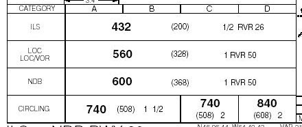
Minima for completing various approaches authorized within this plate are detailed in this area. Straight-in Landing Minima are published for any approach where a normal rate of descent can be made from the Final Approach Fix (FAF) to the runway threshold and the final approach track intersects the extended runway centerline within 30°, both within a prescribed distance from the threshold. When any of these criteria are not met, straight-in minima are not published. See the next section on Circling Minima.
For each approach type on the plate, there are minima published for each aircraft category. These include an altitude ASL in bold print, the value AGL in parentheses in smaller print, then the visibility along with RVR, if the runway is so-equipped. In the example above, the ILS minima is 200 feet AGL and 1/2 Statue Mile, or 2,600 feet on the RVR. For the Localizer only (useable if the glidepath equipment has failed, for example), the minima are slightly higher (the MDA is 560' ASL and minimum visibility is either 1 SM or RVR of 5,000 or more). Notice that these boxes of mininma span the entire width of this section? This is because the minima are deemed safe for all 4 categories of aircraft this approach is designed for, A through D. Please see below for more information on these categories. If there were different mininma for, say Category D, aircraft, each line would span the first three columns and a separate column would be entered for Cat D.
Some approach procedures have Circling Minima published. This allows a pilot to fly an instrument approach procedure for one runway and land on another runway once sighting the runway environment. Circling procedures were detailed here
Prompt compliance with the missed approach procedure is necessary to ensure safety in the climb, since obstacle/terrain clearance is only guaranteed if the missed approach procedure is commenced on or before the Missed Approach Point (MAP). In precision approaches, the MAP is located on the glideslope at the value in the Minima Box appropriate to the aircraft category. In a non-precision approach, the MAP is at the runway threshold where the approach is aligned with the runway, and is designated on the approach diagram if not so aligned.
Additionally, flight times, based on groundspeeds can be to the left of the mininma box. Interpolate as required. If a pilot expects to do about 110 knots groundspeed on final (say an approach speed of 120 KIAS with a ten knot headwind on the ground), the pilot can expect to to reach the MAP about 1 minute, 51 seconds after overflying the FAF.
More DetailsSome approach plates show other details that are not presented in the ILS RWY 29 approach plate already visited.
On some approach plates -- a diminishing number in recent times -- there are published DME ARC Transitions. These arcs are noramlly alinged with airways and form a transition from the enroute phase of flight to the approach procedure.
On some approach procedures, waypoints or fixes are published on the final approach course outside the FAF to allow an aircraf to use RNAV to fly directly to the IF and then fly the straight-in approach procedure from there. The fix named ADRET was first published as an IF for the ILS RWY 29 approach about 25 years ago. The catch is that these fixes, since they're aligned with the FAC, only allow an aircraft to join nearly to the FAC from a range of about 180° off the FAC itself. If flying in from the west, going directly to ADRET in this example has the aircraf toverfly the airport -- it makes for a really tight turn at ADRET.
Most aircraft are equipped with some form of RNAV. Approach design criteria were updated several years ago to provide for Initial Approach Segments based on RNAV to publish transitions in a form similar to those associated with the "RNAV T" design. This allows aircraft to self-navigate from virutally any direction to fly a base leg (if needed) and join the FAC at the IF. At many airports, these waypoints are common to RNAV (GNSS) approach procedures to the same runway -- it helps controllers as the fixes that serve the don't require different names across several approach procedures to the same runway.
Incidentally, the three above examples require ATC clearances before flying to one of the IFs/IAWPs for an approach or before intercepting an arc for a DME arc transition. Additionally, ATC may say something like, "CVA822 is cleared to the SJ NDB via V310, the 10 DME arc and the localizer." This does not allow the pilot to descend below the last cleared altitude. The altitudes published for the arcs, or any other segment of an approach, are simply minimum IFR altitudes for the segment being flown. ATC must authorize the pilot to descend, either by stating an altitude or issuing an approach clearance.
Mentioned earlier, Localizer-only approaches are published at some locations. CYGR, Les Isle de la Madeleine in the Gulf of St Lawrence is an exmaple. There is also a cautionary note directing the pilot to ignore glidepath indications on such a procudure. Since no Glidepath antenna is funcitoning, anything received is obviously an erroneous signal. For the sake of completeness, I'll mention that Localizer Back Course approaches also carried similar notes. These are, indeed, few and far between in today's avation world, but may still exist in some sceneries on older flight simulation software. These were also discussed in the NAVAIDs and Approach Procedures topic in more detail.
A last example of an approach plate comes from Cartwright, Newfoundland. This approach is one of the lettered approaches I spoke of in my NAVAIDs and Instrument Approaches topic where the approach course is not lined up with a runway, effectively making an off-angle, cloud breaking manoeuver based on NAVAID guidance.
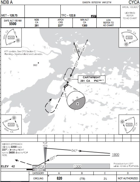
Using the NDB located near the field, an approach procedure was designed using a bearing off the NDB to bring an aircraft down to a point in space where a landing could be completed if visual conditions are encountered in time. First off, the weather limits are much higher for this type of approach than for an NDB, LOC or ILS with straight-in landing minima. This is because the aircraft will break out of cloud and a turn -- possibly of a high magnitude -- will be required, where an approach lined up with the runway would not require much of a turn. Otherwise the approach plate contains all the normal items found on an approach plate. Incidentally, if there were more than one approach of this type based on the NDB used here, the next approach plate would be called an "NDB B", spoken "NDB Bravo", and then "NDB C" and so on, should that many be designed.
Look at some of the notes, just to get a feel for the type of information that can be found. In the Approach Diagram, it is mentioned that this aerodrome and its approach procedure exist with an "ATF Corridor". There is no ATC service provided in this area, as it is all in uncontrolled airspace. That doesn't mean there isn't a fair bit of traffic at this and other aerdromes nearby, as the only way in and out of these sometimes is by air. This is to remind pilots to listen make calls on the ATF not only for the airport, but for an established corridor where ATF procedures apply. More on this can be found in the Canada Flight Supplement (CFS).
The last item I wish to mention is the aircraft categories I've been talking about. These are based on speeds of the aircraft, not specifically weights or sizes. The following table is taken from the AIM, RAC section 9.21.
| CATEGORY | A | B | C | D | E |
| SPEEDS | Up to 90 KT (Includes all rotorcraft) |
91 to 120 KT | 121 to 140 KT | 141 to 165 KT | above 165 KT |
Because different performance characteristics of aircraft require different visibility needs for certain manoeuvers, these categories above have been established to provide obstacle and terrain clearance areas for approach design. Slower aircraft tend to be more mavoeuverable, thereby allowing for smaller areas that may be able to exclude certain obstructions that are further away from the field. You'll notice there are five categories listed above, but most of your approach plates only show A, B, C and D minima. Only certain, high-performance military aircraft (fighers) fall into Category E, and are not provided for in the civil approach plates.
And this concludes our topic for this week. I may have missed something, or left a question or three floating around. Please feel free to e-mail me at mo@xlii.ca if you feel this way. Thanks for reading, and feedback is always welcome.