|
|
|
|
|
This week's topic:
Canada Air Pilot, Part 1: Airport Diagrams
Taking a break (sort of) from the IFR Flight mini-series, this week we'll begin another series on charts. Plans right now are to give an overview of some of the charts used in Canadian aviation. We'll start with the main topic of Charts, and break it down into some of the various categories, then break those categories down into their subparts, where applicable. For example, this week's start on the Canada Air Pilot, or CAP, will include only the Airport Diagrams, and future Subparts will go into more depth on approach plates, RNAV STARs (only the terminology and symbology for this series, the IFR Flight series will provide more on RNAV STARs and flying them later), etc. Let's get started.
Please remember that this series is simply about reading charts, so the diagrams used *will* be (grossly) out of date. Real-world navigation by these particular clips from charts would be a terrible combination of cheap and stupid.
Chart Example
"Outside the Box" Info
"Inside the Box" Info
Frequency Information
ATIS
Clearance Delivery
Ground (with mention
of Apron Advisory)
Tower
Departure/Center
Notes
Declared Distances
Table of Definitions
Bottom Block
RVO and LVO
Take-Off Minima
Chart Scale
Airport Diagram
Runway Information
Taxiway Information
Apron Information
Magnetic Variation
Aerodrome Reference Point
SPEC VIS, Departure Procedures,
SIROs
Other Details
Chart Example
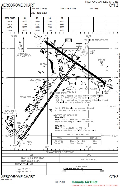
We'll start off with an example of a chart. Have a look at this old airport diagram for CYHZ, Halifax International Airport in Nova Scotia.
There are many parts of interest, here. The information outside the box, including the top and bottom, shows you the "tombstone information" of the diagram. This includes the name of the airport in the top right, along with the location of the airport (in this case HALIFAX/STANFIELD INTL, NS). This can be important, since there are locations across Canada that have the same, or nearly the same, name. Charlottetown, PEI, and Charlottetown, Labrador, for example. And Fox Harbour, NS, and Fox Harbour, Labrador. Each is very different, and they have notes in the approach plates about confirming correct province.
Other important information outside the box lies on the bottom of the diagram. Effective date for the data is listed on the bottom left. Any changes from the previous publication are also listed on the bottom, in the middle. I included a brief look at this information below, when I describe the "Bottom Block". The date of publication is written there, as well. Is this important in VATSIM, or Flight Simulations in general? If your scenery doesn't seem to match up with the diagram chart, check this date. This may be the reason why.
Now the information inside the box. Across the top of the page are a number of boxes. In here, you'll find the radio frequencies and contact information for the various ATC units and facilities you'll be required to talk to on your IFR flight. Have a look below at the enlargement of this area.
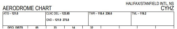
First, the ATIS. This was introduced last week, so I won't go into detail again about it. There are two frequencies listed here for Halifax, the first is VHF and the second is the UHF. In Flight Sim, we don't use the UHF side of things, and there aren't many civilian aircraft equipped with UHF radios, either. You can disregard the UHF entries you read on any of these unless you're flying for the military. A little symbol next to the word "ATIS" that looks like a half moon gives an indication of availability of the service. No symbol means 24 hours a day, 7 days a week, as in this case. The symbol doesn't directly indicate what the hours are, as there is no 'standard', but the airport's entry in the Canada Flight Supplement's facility directory for this airport provides further details. This publication has more to say about services available at any given airport in Canada. Remember that not all airports have an ATIS, so most airport diagrams will not have an ATIS entry.
Next, Clearance Delivery. The real-world abbreviation is CLNC DEL, and in VATSIM, these can be identified as a unit's name ending with _DEL. This is the frequency a pilot would dial up and call when looking for IFR clearance prior to departure. Pretty simple. On initial call, a pilot should give the callsign of the station being called, then provide the callsign of the aircraft, inform which ATIS information code has been received (after all, the last part of any ATIS message in the real world says, "Advise ATC on initial contact you have information 'foxtrot' ") and then confirm the destination as part of the request for the IFR clearance. First call should sound something like this: "Halifax Clearance Delivery, Golf Romeo India November with Infromation Foxtrot. Request IFR to Hamilton."
Wouldn't it be obvious that a pilot is calling for IFR clearance on the CLNC DEL frequency? Sure, but there may be more. A pilot could be calling to advise of a delay, cancellation, or modification of a flight plan, or at some facilities, VFR aircraft are directed to contact CLNC DEL for transponder codes, and other sorts of things that may be specific to a given location. (Another detail provided in the CFS PROcedures section for the airports entry.)
Everyone is familiar with Ground Control (VATSIM callsign _GND). A pilot calls Ground when ready to taxi, right? Sure, but if there is no CLNC DEL frequency listed in this bar, it means Ground is the one to contact for IFR clearance, too. Most airport aprons in Canada are uncontrolled, Halifax is no exception. A note in the aerodrome diagram tells aircraft on the apron to "Monitor 121.9 for all apron movement. Ctc gnd ctl 121.9 after pushback for taxi clearance." If the apron is controlled, there should be a note somewhere on the plate, whether the frequency is listed like any other in this bar, or in a note in the airport diagram itself. Another note for those is that apron control is not normally an air traffic control facility; it's usually staffed by the airport.
In any case, GND is the station to call for authorization to proceed on the taxiways and runways (also known as the "maneuvering area" of an airport). "Halifax Ground, Romeo India November ready for taxi". In the case of an airport with an ATIS, the runway to expect would be the active runway mentioned on the ATIS information, although a pilot can always request the use of another runway. ATC may say it's not available, but there's no harm in trying. Any taxi clearance including a "Hold Short" instruction must have the Hold Short instruction readback in full. This includes to hold short of any taxiway, intersection, even a pavement marking. You may be asked to hold short for a variety of reasons, but normally these will be in regard to other traffic. Our trusty AIM has another note regarding reading back "hold short" instructions. It tells us the phrase holding short is not an instruction, but rather a location and need not be read back. The point is this: ATC may say something like, "Romeo India November, taxi to Runway Zero-Five via Alpha and Bravo. Contact Tower 118.4 holding short." In this phraseology, the instruction to Hold Short of the runway is implied and applies, according to Canadian Aviation Regulations (CARs), but this "holding short" statement is an expression of when GND is instructing you to contact the Tower controller: when the aircraft is holding short of the runway. Until the aircraft is at that point, the pilot should continue to monitor GND in case something else comes up prior to reaching that point.
One more thought about taxi instructions. Sometimes a runway must be crossed on the way to the intended departure runway. Looking at the airport diagram for CYHZ, an aircraft that wants to leave the main terminal apron and take-off from Runway 32, must taxi via Delta, cross Runway 05/23, then use Kilo to reach the threshold of Runway 32. Two points to be made: The ground controller should explicitly state a runway crossing instruction if allowing the aircraft to cross a runway and the AIM tells us that, while crossing instructions don't require a readback under CARs, readbacks of such instructions are recommended as a cross-check. Runway incursions are a serious safety hazard, and occur in the real world far too often, so anything that might help is probably a good idea.
We'll move on to Tower, but there is another point to be made with respect to taxi instructions as they relate to runway crossing instructions.TWR is the Tower. Straight forward. GND will normally give a pilot instructions as to when to switch to tower frequency, but it is perfectly allowable once a pilot reaches the runway to be used for take-off that the pilot call the Tower, even if not so instructed. These instructions are normally provided with taxi clearance. Other times, GND will give the instructions to switch at a later point. This is largely a local thing, but also depends heavily on what was given for taxi instructions and even the airport layout. If a pilot were told to hold short of a runway that must be crossed enroute to the departure runway (as with our Runway 32 example above), a further authorization is required to cross it. GND may issue further crossing instructions when traffic permits, in which case a frequency change would neither be desired nor issued. GND may instruct a pilot to contact TWR at that point with the intent of having the TWR controller issue the further taxi instructions. In either case, the pilot should listen carefully to what's issued: "Expectation bias" is a phenomenon whereby someone hears what was expected instead of what was said. Whether you're the controller talking to the pilots, or the pilot listening to the controller, keep this in mind. This is part of why readbacks of clearances have become a thing in the first place.
TWR will normally issue clearances to aircraft that allow entry to the take-off runway to line up for take-off but wait for further instructions before issuing the take-off clearance (phraseology: "line up and wait"), or just clear a pilot for take-off while still on the taxiway, which allows the pilot to enter the runway, line up with the centerline, and commence the take-off roll. TWR will normally give a pilot instructions about when to contact the departure controller as well, quite typically with take-off clearance unless there is a reason to hold on to an aircraft after take-off.
Lastly, Departure. This is the frequency in use by the departure controller, the first controller an IFR pilot will talk to once airborne. Tower will likely provide a pilot with this frequency but if it is not provided, or the pilot misses it, it's written down right here.
Whether in VATSIM or the real world, the departure position is not always staffed separately. In which case, the Terminal controller (abbreviated TML in the real world) or the Approach controller (_APP in VATSIM) is the one to contact -- that frequency will be listed on this chart, as well.
In a previous topic I already mentioned this, but I'll say it again here: If the unit name is omitted in the publication and just the function is listed, the unit name is the name of the airport. For example, the TWR in this case is "Halifax Tower", and the departure controller is "Halifax Departure". If the unit is not at the airport where you're flying, the unit name will be mentioned in addition to its function. Charlottetown, PEI, for example, doesn't have its own terminal control unit providing APP/DEP functions. The airspace around it is controlled by Moncton Center. A look at CYYG's airport diagram, reveals arrival and departure functions are provided by "Moncton Center" on 135.65, rather than "Charlottetown Departure" or "Charlottetown Arrival".
Also, not all airports have all the services mentioned in the list above. Some airports may have more. Where something detailed above doesn't exist at the airport, it just won't be listed. Where something not mentioned above exists, there will be an additional entry. Again, checking the airport's listing in the Canada Flight Supplement will reveal more details, including hours of operation for "limited hours" sections, etc.
Next, we'll look at the Declared Distances section of the chart.
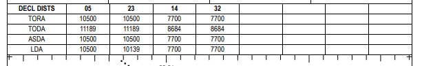
These abbreviations all refer to distances available for different operations, and include different lengths in some cases. You'll notice that they are all basically the same. I'll give you some idea of what they mean in the table below.
| Abbreviation |
Short for |
Meaning |
| TORA |
Take-Off Run Available |
The length of runway declared
available and suitable for the ground run of an aeroplane taking
off. |
| TODA |
Take-Off Distance Available |
The length of the TORA plus
the length of the clearway, where provided. See below. |
| ASDA |
Accelerate Stop Distance
Available |
The length of the TORA plus
the length of the stopway, where provided. See below. |
| LDA |
Landing Distance Available |
The length of runway declared
available and suitable for the ground run of an aeroplane landing. |
The Clearway mentioned above in TODA refers to an area of land cleared of obstacles that would allow for an aircraft to accelerate in ground effect once airborne. Current standards allow for a maximum of 1,000 feet for a clearway, but all of the clearway must lie within the airport boundaries. The idea is that the airport authority has control over the erection of obstacles and growth of trees, thereby allowing the aircraft the use of the airspace at least up to a certain height.
A Stopway mentioned in ASDA, refers to an area at the end of a runway that is not suitable to high-speed operations like the latter portion of the take-off run, but may be suitable for use for deceleration in the event of an aborted take-off. A stopway will be marked with yellow chevrons spanning the entire width of the stopway. A stopway is not considered useable for taxiing, or for the beginning of the take-off roll if departing in the opposite direction.
These distances are declared for each runway available at the airport.
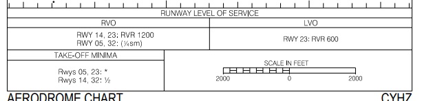
There are two boxes starting this section off in this particular example of CYHZ, but these aren't applicable everywhere. These represent RVO and LVO, or "Reduced Visibility Operations" and "Low Visibility Operations", respectively. At some airports, where deemed necessary, operations in poor weather either can be, or has been, proven hazardous. To that end, the airport authority has planned operations for Reduced and Low Visibility conditions. This is not an ATC-driven item, but must be published. Procedures will be published on a separate plate, normally located near the airport diagram, if this box exists. Typically, once the weather drops to the numbers published (visibility or RVR, if available), ATC must revert to the qualifying procedures based on the criteria. This means restrictions. Only certain taxi routes will be available, perhaps one or more runways will not be authorized for use, and it may even mean that only one aircraft is permitted in certain areas at a time -- perhaps that area is the entire maneuvering area, including taxiways and runways.
On the left, we see the "Take-Off Minima" block. I described this in much more detail in the "better late than never" Part 2a for the IFR Flight Series. I won't reiterate that information, but remember it is vitally important to be read and understood clearly, especially if there are any special instructions for the runway you plan to depart. In this case, there are no special procedures, and the standard take-off minimum of 1/2 statute mile applies, but for runway 05/23, there are notes regarding trees that pilots should be aware of, just in case the take-off doesn't go quite as planned. As long as the weather shows 1/2 mile for visibility on the METAR sequence, a pilot meets the minimum visibility for take-off from any runway at CYHZ. Please note that, as discussed in the prvious article, a "Departure Procedure" is not quite the same as a "Standard Instrument Departure", or SID. I encourage you to read both parts (Part 2 and Part 2a) to learn the difference. At most airports where SIDs are published, pilots can expect to be assigned a SID as part of their IFR clearance.
Then the scale for the airport diagram. This could be useful for determining distances remaining from intersections of taxiways and runways. Sometimes a pilot might request a departure from the intersection of a runway and a taxiway further along the runway, just to save on taxi time. For example, if Runway 32 is active at Halifax, you can see that taxiing for departure on runway 23 by Golf and Foxtrot means that one would have to taxi across Runway 14/32 and on to Lima to get to the threshold, or onto runway 14/32 for about 1,000 feet if taking off from Runway 23 from the intersection of Runway 14/32. Either might pose some delay. Some quick figuring with the scale would reveal approximately 2,000 feet less runway available if the pilot were to request an intersection departure from on Runway 23 from Echo, instead. Depending on the aircraft type, something on the order of 8,500 feet could be plenty? Even Delta would allow for more than 7,000 feet of runway off Runway 23. It would save some taxi time. Now, for those in a single engine aircraft, consider just how useless runway behind you is if your engine should fail on take-off...
I'll briefly look below the boxed information here, too. At the bottom left, the effective date for the information in the diagram is published. (I told you this plate was stale) Also, the change from the previous publication, if any at all, is listed. Sometimes it is just an editorial change, nothing of significance. If a new building was added, a new obstacle built, or a runway or taxiway decommissioned, this type of information would all be mentioned here.
Last, but certainly not least, is the airport diagram itself.
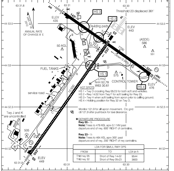
There really is a lot of information here. First off, the runways will be "shaded" black. Additional details, visible in Runway 23 in this diagram, include lighting associated with Category II (or III at certain other airports) ILS. In this case, runway 23 has centerline lighting (CL - the white circles down the length of the runway) and Touchdown Zone Lighting (TDZL) near the threshold. The diagram doesn't really do TDZL justice, as it normally extends to 3,000 feet from the landing threshold. Near the runway thresholds, the runway numbers will be printed, along with the magnetic heading (or true heading, followed by "T" if the runway is designated by true heading) and the runway threshold elevation in feet ASL. Runway length is also marked alongside the runway graphic, as will runway width if other than the standard 200-foot width. In the case of Runway 32 at CYHZ, the runway also has a significant downslope. This is calculated the same way slopes are calculated for roads and highways, but they appear for lower values than they do on roads. They look at the average drop from one end of the runway to the other (unless otherwise noted) over each 1,000 feet of runway length. In this example, 476 - 435 = 41 feet. 42/7700=0.0054, or 0.54% down along the length of the runway. This can, therefore, be interpreted as 5.5 feet of elevation change for each 1,000 feet of runway length. For a highway, this means little. For an aircraft trying to decelerate from 140 knots on an icy runway, it means quite a bit. It might be better to use a runway with less slope even if it has a crosswind. Many flight simulation programs portray this much more accurately than in the past.
Taxiways will be outlined in black, and somewhere near the segment will be printed the name of the taxiway. Taxiways are named with letters to distinguish them from runways. At larger, more complex airports, taxiways will often have designations including numbers with the letters, like "W1, W2, W3, ..." These will normally be grouped together with some a logical placement on the field.
When you get to Aprons, you'll often see Roman Numerals printed. These indicate Apron I, or Apron VIII or whatever, and a pilot should use these designations when calling in to Ground to let the controller know where the aircraft is located are. If the aircraft is parked at a gate, the gate number is better used instead. Some examples, are:
There are also other forms of symbols shown on aprons. Some airports have de-icing spots published, helipads, or other such data. These are normally labeled if they are not drawn with a standard symbol.
Magnetic Variation will also be indicated in the airport diagram. This can be used to determine winds in Degrees Magnetic from a METAR weather sequence which reports winds in Degrees True. In the case of Halifax with 20° west, you would add the 18° (round off to 20) to the METAR wind direction to get the magnetic direction of winds, so if you saw 09027 on a METAR, the winds at Halifax would be 110°M at 27 knots.
The Aerodrome Reference Point, or ARP is also included. This is the point published in the Canada Flight Supplement, and is the point used when designing approaches and providing for clearance from off-airport obstacles and other such items. I don't believe this is of any practical value to a pilot, but I could be wrong.
Any special notes about departure procedures (again, not the SIDs), or SPEC VIS will be placed in the airport diagram. Other information will find its way in here, too, like the distances declared for Land And Hold Short Operations (or LAHSO for short). These are all LDAs so no stopway is provided, since the idea is to stop and hold short of the crossing runways. These distances will include the standard 200 feet clear of the runway the cross, from the closest edge. See the examples below:
Other items marked on this sort of chart include prominent obstacles (which could include radar antennas, ASDE installations, communications towers, etc), service roads (to help pilots identify that the piece of pavement calling their name is not a taxiway), or other dangers like fuel tanks and terrain or obstruction lights (like the one shown just to the west of the threshold of Taxiway B in this example). The aiport beacon for the airport is marked so pilots can get a feel for where they are if they see this, as is the control tower, to aid the pilot in interpreting just how well the TWR should be able to see things near the aircraft. Windsocks will be marked (lighted ones will have little strokes emanating from them), as well, to show the pilot where to can look for one of these to confirm winds while landing, taking-off or taxiing. Also, NAVAIDS on, or very near, the field will be marked as well, including DME, VOR, NDB, and even things like RVR (Runway Visual Range) equipment (the little "pie shapes" with A and B marked in them in this example). "Hot spots", or common conflict areas on the airport surface will be circled on the chart and described in text. Oh, yeah, latitude and longitude lines are provided for reference, also. A lot of items beyond what I've listed and noted can appear on these diagrams, too.
Other CAP charts will be discussed in other articles. You may reach me via e-mail at mo@xlii.ca. Thanks again for the support. It's nice to know that people are reading this information and finding it useful. Feedback, good or bad, is always welcome.