|
|
|
|
|
This week's topic:
IFR Flight Part 2a: Departure Procedures
I inadvertently skipped a very important part of IFR departures when I did IFR Flight Part 2: Departures in April, 2003. Two things called this to my attention. Some real world problems in the Moncton FIR faced by one particular aircraft operator at one of our airports at the time, and the previous weekly topic on Holds. The item I missed? Departure Procedures. What are they? Let's find out.
What is a Departure Procedure?
I wrote about SIDs, but a Departure Procedure another, related topic. It's kind of like a SID in one respect, but very unlike them in many others. If a SID (or more than one) is provided at that aerodrome, a SID plate (perhaps two pages) will be published with both a graphical and textual representation. Since I covered SIDs in IFR Flight Part 2: Departures in this series, I won't repeat myself.
For every aerodrome with an instrument approach procedure published in the Canada Air Pilot, there will also be a published aerodrome diagram. These diagrams contain more information than just the "top down" view of the airport. They also contain information regarding latitude and longitude, magnetic variation, radio frequencies and, most importantly, departure information. If no special departure procedure is published for the airport, a Normal Departure Procedure can be used. What's normal? Hard to define for many topics, but for this, the AIM, section RAC 7.7 has a definition.
Standard Departure ProcedureA Departure Procedure is a set of instructions that ensures obstacle and terrain clearance for an IFR aircraft departing an airport, or more specifically, a given runway at an airport. When procedure designers are assessing a runway, they look first at a set of criteria that any normal IFR aircraft can attain. That criteria includes and expectation that an IFR departure will:
One can make some assumptions about the departure path that assessed from these numbers. An aircraft will, under these criteria, be permitted to fly straight ahead off the runway for as much as 2 NM before making a requested turn. That does not mean a pilot must fly straight ahead for 2 NM. Just that the obstacle clearance is assessed as though that were the case. Most aircraft are capable of exceeding this rate of climb, and as such will reach the 400 feet AAE well inside the 2 NM -- meaning that they're at a safe altitude to commence a turn. The allowance is more of a worst case scenario, and climbing faster is both better for getting on course sooner and missing obstacles and terrain. Plus, following aircraft may be more likely to be issued a take-off clearance (or be permitted to take-off in terms of the IFR clearance) if the preceeding aircraft climbs quicker.
There are many cases where this kind of departure procedure cannot be accommodated. Mountainous terrain, restricted airspace, obstacles such as transmission towers near the departure path, etc. We'll look at some examples of some situations and how and where they're normally published.
Basics of an Aerodrome Diagram in the CAPHave a look at the following, grossly-outdated aerodrome chart for Halifax International (CYHZ), which is a pretty straight forward layout:
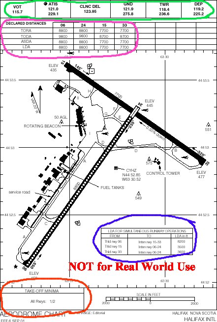
You can see here the parts I want to call your attention to. Not all airport diagrams contain the same information, but some of it is standard and may be seen in most, if not all, aerodrome charts. Circled in green at the top are the frequencies you are to use when calling the various ATC units or functions. The callsign for the unit will be the name of the airport, unless otherwise specified, and the function, and the frequency is listed. For this example, on take-off from CYHZ, a pilot should call "Halifax Departure" on 119.2. If it were another unit, the name will be specified directly.
In an awful shade of pink/purple, the declared distances for each of the runways are noted. These two items, among others, are standard information published for an airport diagram, though not all airports will have the same ATC units or functions listed here.
How about some non-standard items? In blue, down near the bottom, the declared landing distances for Land And Hold Short Operations (LAHSO) are stated. These include useable runway up to to the point where an aircraft will not be considered "infringing" on the crossing runway, and the offset will be 200 feet from the side of the runway closest to the edge of the crossing runway. This is one type of information that won't be found on every approach plate, even if the airport does have intersecting runways as not all airports are approved for such an operation.
Finally, the important part of what we're looking for in this topic, the Take-Off Minima, circled in red, and these are located in the bottom left hand corner. What are the Take-Off Minima? I'm so glad you asked. The numbers presented here are the lowest visibility, in statue miles in which a pilot is legal to commence a take-off from a particular runway. I chose Halifax to start off with in this section for its simplicity: For all runways at Halifax, the minimum legal visibility requirement is 1/2 mile. If visibility is less than that, a pilot is not allowed to commence a take-off, unless some other provisions can apply.
It's quite likely at some airfields that different minima will apply to one or more runways, too. If that's the case, one of two notations in this box at the bottom left will appear:
In some runway environments, it may be deemed that more than 1/2 SM is required for safety, so it may be noted that the minimum visibility is 1 SM, 3/4 SM, or whatever. Helicopters, due to their capability for slower speeds, are authorized to use 1/2 the Take-Off Minima published, but never less than 1/4 SM.
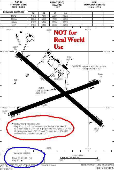
If you see an asterisk next to a runway number, or an asterisk in place of any other information in this box, look in the Airport Diagram above. I've called on one of my favorite airports, CYFC, Fredericton, NB. Why is this one of my favorites? Because its close proximity to CYR724 makes life so much fun. The northern border lies just 3.5 NM off the end of Runway 15 and it is home to a military training ground which hosts "continuous live firing", surface to FL250. This situation causes all kinds of problems in the real world, since many pilots seem to flightplan through it or forget about it once they get in the air. This airport is a case where the Departure Procedure will contain more than just the take-off minima in the box at the bottom left. Have a look at the also-grossly-outdated image to the left. The airport layout has changed, Runway 09/27 has been extended to 8,000 feet (the extension on the west side of the runway), but the airspace around it is still the same.
Circled in blue at the bottom is the Take-Off Minima box. It includes the standard 1/2 SM for runways 09, 27, and 33, but also shows an asterisk for runway 15. This asterisk is attempting to call attention to the alternate minima and departure instructions associated only with Runway 15 at CYFC. I have circled these in red in the airport diagram above the box. For Runway 15, because of the restricted airspace, there are specific instructions in addition to the minimum visibility for take-off. The Take-Off Minimum for the runway is 1/2 SM, like the others but instead of the 200ft/NM no turns below 400 stuff above, the chart states "Turn as soon as practicable after take-off to remain clear of CYR724". Unless flying an A-10 and can take a few hits, a pilot should really follow this instruction. The chart gives a radial (the 231 radial to be exact) from the YFC VOR to stay north of to help a pilot know when the aircraft is OK with respect to this airspace. A speed restriction for higher performance aircraft (CAT 'C' and 'D' aircraft) is stated to help confine the aircraft's turns to a shorter radius which will, in turn, help ensure the pilot has a better chance of staying out of the restricted area. Once assured clear of the airspace, normal speed for the aircraft type involved may be resumed.
It cannot be stated enough: This is a very old chart. Departure instructions have changed as of late 2020. This chart is meant only as an example of what to look for, not what should be flown at CYFC today.
Have a look now at this clip from yet-another-outdated chart for Wabush, NL (CYWK). There are some other notes which will apply to this airport. Because of high terrain located just north of the airport, aircraft departing runway 01 are required to climb at a minimum gradient higher than the standard 200 feet per nautical mile for a normal IFR Departure Procedure (DP), or a SID. If the requirement is higher than 200 ft/NM, the number required will be published along with an altitude at which a lower gradient can be established safely. I haven't yet seen a DP like this that has a higher climb gradient than the standard but isn't accompanied by a little chart that helps to figure out the required rate of climb based on an expected ground speed. For example, if a Dash 8 plans to climb out at 150 KIAS, consider winds (10 knot headwind on the ground for this example) and estimate what the ground speed is likely to be (150 minus a headwind of 10 knots, so likely around 140, we'll say), then look up that value in the table to determine the required rate of climb in feet per minute to meet the required gradient. In this example, a climb rate of 560 feet per minute should keep a pilot from trimming the trees or eating granite). Also, because of terrain surrounding the airport, there are heading requirements. Following the directions as published will keep an aircraft in safe air.
Note the second section in the DP, called SPEC VIS. This is Specified Visibility for an alternate Departure Procedure. Here at Wabush, if better weather conditions permit, the pilot may elect to ignore the heading and altitudes in the first section and climb under visual conditions to 2,400 feet, then make the turn to 039°. Upon reaching 3,400, proceed on course as cleared by ATC. Both of these apply to runway 01 only, so far.
Runway 19 has special considerations as well. 1/2 SM visibility, for starters. Since the terrain isn't right off the departure end, but rather lies east and west of the departure path for Runway 19, the text here only prohibits turns below 2,500 feet.
Some airports are more complex than these. You'll love this next example.
This is ugly. And it's not the worst. The first DP is for runway 03T. The 'T' simply means that at this airport, you're using True heading rather than Magnetic to determine direction (this is due to significant compass errors because of the proximity to the magnetic north pole). First off, you can't depart using this DP if you're in something faster than a CAT B aircraft. If so, you have to refer to the second section for SPEC VIS and hope the weather cooperates.
This takes some time to familiarize youself with. It may be helpful to take out the LO En Route chart to look at the NDB placement that you'll have to navigate to, and even the approach plates for the airport while you're planning your flight. In fact, some DPs include a reference to a published missed approach procedure for the aerodrome in question. Being prepared is always a good idea. In this case, you can see that some turns are required, minimum climb gradients are significantly higher than normal (almost double the standard 200 ft/NM), and, best of all, there is one of those 'shuttles' I mentioned last week in Part 4, Holds. There's even a speed restriction in the shuttle procedure to help confine the pattern. What a great airport. Ever feel pinched in the climb?
So you see, there really is more than meets the eye to the "unrestricted climb" as I called it in the original Part 2. Just because ATC doesn't assign a pilot anything specific doesn't mean an aircraft can just firewall the throttles and go. ATC is usually aware of special conditions, so a controller shouldn't assign you a left turn if left turns aren't permitted off a certain runway, for example. But ATC also won't assign a pilot conditions which are part of a published Departure Procedure, either. A pilot should review this sort of documentation for the airport before calling for clearance. That way, if something doesn't make any sense, there is plenty of time to discuss it with the controller rather than getting the air, getting into cloud and starting to question that which can no longer be seen. ATC restrictions are meant for traffic, not for all the specifics of the airport environment. ATC will separate aircraft from aircraft, but the pilot must keep the aircraft separated from the environment.
I was surprised that nobody mentioned this oversight to me. Frankly, I was surprised I didn't even think about it, as important as it is. I apologize to all those who read and didn't get this information from the original topic, and hope that this filled in a gap. Any feedback to send? Please send it to me at mo@xlii.ca. Thanks to all those who have expressed their gratitude to me, and to all of you who are reading this regularly.